You're about to create your best presentation ever

Powerpoint Uml Template

Create your presentation by reusing a template from our community or transition your PowerPoint deck into a visually compelling Prezi presentation.

UML

Transcript: Behaviour Composite Interaction Diagram Two Views of System Model similar to the activity diagram both visualizing a sequence of activities. The difference is that the individual activity in the interaction overview diagram is pictured as a frames, which can contain interaction - or sequence diagrams Composite Structure Diagram Activity models the physical deployment of artifacts on nodes Categorized Hierarchy of UML Diagrams Diagram An Overview Diagram Group 11 Package Sequence a diagram that shows a complete or partial view of the structure of a modeled system at a specific time. - graphical representations of workflows of stepwise activities and actions with support for choice, iteration and concurrency. - diagram shows the overall flow of control. emphasizes the static structure of the system using objects, attributes, operations and relationships. Thank You! Structure Diagram Object Diagram Colimay Lizardo Macandili Mangilin State Machine Diagram shows object interactions arranged in time sequence State emphasize the things that must be present in the system being modeled emphasizes the dynamic behavior of the system by showing collaborations among objects and changes to the internal states of objects. Diagram Structure a type of static structure diagram, that shows the internal structure of a class and the collaborations that this structure makes possible. -fyrevolt Interaction Overview Diagram Unified Modeling Language Package Diagram Profile Interaction -depicts how components are wired together to form larger components and or software systems. They are used to illustrate the structure of arbitrarily complex systems. models the interactions between objects or parts in terms of sequenced messages. Communication diagrams represent a combination of information taken from Class, Sequence, and Use Case Diagrams describing both the static structure and dynamic behavior of a system. Object Diagram Timing Diagram Diagram Diagram graphical representation of a user's interaction with the system and depicting the specifications Static view <Structural> Deployment Diagram used to explore the behaviors of objects throughout a given period of time. A timing diagram is a special form of a sequence diagram. The differences between timing diagram and sequence diagram are the axes are reversed so that the time is increased from left to right and the lifelines are shown in separate compartments arranged vertically. Communication Diagram -operates at the metamodel level to show stereotypes as classes with the <<stereotype>> stereotype, and profiles as packages with the<<profile>> stereotype. The extension relation (solid line with closed, filled arrowhead) indicates what metamodel element a given stereotype is extending. Component Diagram Diagram Diagram Activity Diagram Behavior Diagram Interaction - a set of graphic notation techniques to create visual models of object-oriented software-intensive systems. Sequence Diagram emphasize what must happen in the system being modeled Diagram a significantly enhanced realization of the mathematical concept of a finite automaton in computer science applications as expressed in the Unified Modeling Language (UML) notation. Structure Timing Component a kind of interaction diagram that shows how processes operate with one another and in what order portray the different types of users of a system and the various ways that they interact with the system Dynamic view <Behavioral> Profile Diagram Use Case Diagram Use Case Diagram Diagram the main building block of object oriented modelling Diagram emphasize the flow of control and data among the things in the system being modeled. Machine Diagram - used to specify, visualize, modify, construct and document the artifacts of an object-oriented software-intensive system under development. depicts the dependencies between the packages that make up a model. Class Diagram Deployment Diagram represent both the main objects, interactions in the application and the classes to be programmed. Diagram Class Diagram Communication Diagram Overview

UML

Transcript: Grady Booch , Jim Rumbaugh , and Ivar Jacobson developed UML in the mid 1990s In 1997, UML 1.0 was submitted to the Object Management Group. UML 2.0 provides 13 different diagrams Unified Modeling Language used to show the dynamic communications between objects during execution of a task. It show temporal order in which message are sent between the objects to accomplish task. Unified Modeling Language Object Constraint Language depicts the dynamic behavior of a system or part of a system through flow of control between actions that system performs. Unified Modeling Language provides a static or structural view of a system. UML Deployment Diagram Deployment Diagram Activity Diagram Communication Diagram models an object's states, the actions that are performed depending on those states, and the transitions between the states of the object. State Diagram Unified Modeling Language State Diagram CONTEXT PROPERTY OPERATIONS KEYWORDS helps you determine the functionality and features of the software from the user's perspective. Object Constraint Language Activity Diagram standard language for writing software blueprints maybe visualize , specify, construct, and document artifacts of software -intensive system Communication Diagram Sequence Diagram provides another indication of the temporal order of the communications but emphasizes the relationship among the objects and classes instead of the temporal order. Class Diagram Sequence Diagram user Use - Case Diagram Class Diagram Sequence Diagram complements UML by allowing you to use formal grammar and syntax unambiguous statements about various design model elements focuses on the structure of a software system and is useful for showing the physical distribution of a software system among hardware platforms and execution environments. Use - Case Diagram

UML

Transcript: State diagrams are a type of directed graph, in which the graph nodes represent states and labels on the graph edges represent actions. For example, here is a state diagram representing the life cycle of a chicken: 2.Wolf-goat-cabbage puzzle 3.Phone lattices 4.Representing functions 5.Transition functions 6.Shared states 7.Counting states 8.Variation in notation UML Object Diagram Overview: Object diagrams are derived from class diagrams so object diagrams are dependent upon class diagrams. Object diagrams represent an instance of a class diagram. The basic concepts are similar for class diagrams and object diagrams. Object diagrams also represent the static view of a system but this static view is a snapshot of the system at a particular moment. Object diagrams are used to render a set of objects and their relationships as an instance. Purpose: The purpose of a diagram should be understood clearly to implement it practically. The purposes of object diagrams are similar to class diagrams. The difference is that a class diagram represents an abstract model consisting of classes and their relationships. But an object diagram represents an instance at a particular moment which is concrete in nature. It means the object diagram is more close to the actual system behavior. The purpose is to capture the static view of a system at a particular moment. So the purpose of the object diagram can be summarized as: •Forward and reverse engineering. •Object relationships of a system •Static view of an interaction. •Understand object behavior and their relationship from practical perspective Andy G. Dizon Any Questions? Thank you! Unified Modeling Language State & Object Presented by: UML Diagram UML State Diagram

UML

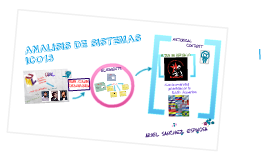
Transcript: UML USE CASE - UML HISTORICAL BACKGROUND Conclusion The unified Modelling Lenguaje (UML) is a lenguaje and notation system used to especify,construct,visualize and document models of software systems. UML is not a methodologhy(which considers the specific framework and conditions of an application domain the organizational environment and may other things. THE RESULTS WERE NOT ALWAYS AS GOOD AS EXPECTED - MANY SYSTEMS ENGINEERING COMPUTER AIDED SOFTWARE (CASE) WERE LITTLE MORE THAN REPORT GENERATORS THAT EXTRACTED DESIGNS AFTER THE IMPLEMENTATION WAS FINISHED, BUT GOOD IDEAS INCLUDED METHODS THAT WERE USED EFFICIENTLY IN SOME CASES IN BUILDING LARGE SYSTEMS. THE COMMERCIAL APPLICATIONS WERE MORE RELUCTANT TO ADOPT AA LARGE CASE SYSTEMS AND DEVELOPMENT METHODS. MOST SOFTWARE DEVELOPED ITS BUSINESS INTERNALLY AS NEEDED, WITHOUT THE ADVERSARIAL RELATIONSHIP BETWEEN CLIENT AND CONTRACTOR THAT CHARACTERIZED THE MAJOR GOVERNMENT PROJECTS. COMMERCIAL SYSTEMS WERE PERCEIVED AS SIMPLER, WHETHER THEY WERE TRUE OR NOT, AND THEREFORE HAD LESS NEED FOR A REVIEW BY AN EXTERNAL ORGANIZATION. The UML language began to take shape in October 1994, when Rumbaugh joined Rational company founded by Booch (two respected researchers in the area of software methodology). The goal of both was to unify two methods were developed: the Booch method and OMT (Object Modelling Tool). The first draft appeared in October 1995. At the same time another well-known researcher, Jacobson joined Rational and his ideas were included. These three are known as the "three friends". Furthermore, this language was open to collaboration with other companies to provide their ideas. These collaborations led to the definition of the first version of UML -A use case describes, from the point of view of the actors-a group of activities of a system that produces a concrete and tangible result. Use cases are descriptions of typical interactions between users of a system and the system itself. Represent the external interface of the system and performance requirements specify what must have this (remember, only what, not how). When working with use cases, it is important to remember some rules: Each use case is related to at least one actor Each use case is an initiator (ie an actor). UUML is not a programming language. The tools can Provide UML code generators for a variety of programming language, and build models for reverse engineering from Existing programs.The UML notation is derived from and unifies the three methods of analysis and extended designs.Grady Booch Methodology for Describing sets of objects and Their relationships.Technical modeling objectoriented James Rumbaugh (OMT: Object - Modelling Technique).Approximation of Ivar Jacobson (OOSE: Object-Oriented Software Engineering) by the method of use cases (use case). UML HISTORICAL CONTEX DEVELOPING METHODS FOR TRADITIONAL PROGRAMMING LANGUAGES SUCH AS COBOL AND FORTRAN, EMERGED IN THE 70'S AND BECAME WIDESPREAD IN THE 80. FOREMOST AMONG THEM WAS STRUCTURED ANALYSIS AND STRUCTURED DESIGN [YOURDON-79] AND ITS VARIANTS SUCH AS REAL-TIME STRUCTURED DESIGN [WARD-85] AND OTHERS. THESE METHODS ORIGINALLY DEVELOPED BY CONSTANTINE, DEMARCO, MELLOR, WARD, YOURDON, AND OTHERS, REACHED SOME INSIGHT INTO THE AREA OF LARGE SYSTEMS, ESPECIALLY FOR PROJECTS CONTRACTED BY THE GOVERNMENT IN THE FIELDS OF AEROSPACE AND DEFENSE, IN WHICH CONTRACTORS INSISTED ON A DEVELOPMENT PROCESS ORGANIZED AND COMPREHENSIVE DOCUMENTATION OF THE DESIGN AND IMPLEMENTATION OF THE SYSTEM. UML has been promoted and accepted as standard from the OMG, which is also the origin of CORBA, the industry leading standard for distributed object programming. In 1997 UML 1.1 was approved by the OMG becoming the de facto standard notation for analysis and object-oriented design. UML is the first method to publish a meta-model in its own notation, including notation for most of the information requirements analysis and design. It is therefore a meta-model self-referential (any language general-purpose modeling should be able to shape one's self). And one more thing... SYSTEMS ANALYSIS TEST DIAGRAM OF CASE The use case diagrams describe the relationships and dependencies among a group of use cases and actors involved in the process. Importantly, the use case diagrams are not intended to represent the design and can not describe the internals of a system. The use case diagrams are used to facilitate communication with the future users of the system, and the customer, and are especially useful in determining the characteristics necessary to be the system. In other words, use case diagrams describe what the system should do but not how.

Now you can make any subject more engaging and memorable