Use Case Diagram
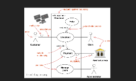
Transcript: Actors What are Use Case Diagrams? Significance of Use Case Diagrams Purpose and Benefits Actors represent external entities that interact with the system, such as users, systems, or devices. Proper identification of actors is essential to model system behavior accurately, ensuring that all interactions are represented and the needs of users are addressed. A Use Case Diagram is a UML representation illustrating the interactions between actors and a system, showcasing specific functionalities available to users. It serves as a crucial tool for understanding user requirements and system capabilities. They offer a high-level overview of a system's behavior, making them essential for stakeholders, developers, and analysts in defining system functionality. Use case diagrams bridge communication gaps between technical and non-technical team members. Use Case Diagrams help in gathering and clarifying user requirements, ensuring alignment with user needs during the design phase. They also clearly define system boundaries, distinguishing between internal components and external actors. Include Relationship Use Cases Association Relationship System Boundary Use cases are specific functionalities the system provides, represented as ovals in diagrams. Examples include actions like 'Place Order' or 'Track Delivery'; they clarify the distinct operations available to actors within the system's context. The Association Relationship signifies the communication between an actor and a use case, depicted by a line connecting them. For instance, in an online banking system, a line links a customer to the 'Transfer Funds' use case, illustrating the customer's involvement in this functionality. The Include Relationship indicates that a use case incorporates the functionality of another use case, represented by a dashed arrow. For example, in social media applications, a 'Compose Post' use case includes an 'Add Image' functionality, showing how they work together to enrich user interactions. The system boundary delineates what is inside and outside the system being modeled. Represented by a rectangular box, it clarifies internal system components from external actors, highlighting the scope and limits of functionalities provided by the system. Extend Relationship Drawing Use Case Diagrams Tools and Platforms Example: Online Shopping System The Extend Relationship represents optional functionality that can enhance a use case under certain conditions, shown by a dashed arrow. For instance, an 'Online Purchase' use case could extend to include 'Offer Discount' under specific circumstances, providing flexibility in functionality without altering the base use case. Creating a Use Case Diagram involves identifying actors, defining use cases, and setting system boundaries. This structured approach visually represents user interactions and ensures alignment with user requirements, clarifying the system's functional scope. Popular tools for creating Use Case Diagrams include Lucidchart, Microsoft Visio, and StarUML. These tools offer intuitive interfaces and robust features, enabling both technical and non-technical users to design diagrams effectively. In an Online Shopping System, use cases like "Place Order" and "Track Delivery" exemplify user interactions. The actors include customers and administrators, showcasing the diverse functionalities that cater to different user needs. Common Mistakes and Best Practices Common mistakes in Use Case Diagrams include failing to identify all actors or overly complex use cases. Best practices involve keeping diagrams simple, validating with stakeholders, and revising based on feedback to ensure clarity and utility. Understanding Use Case Diagrams in UML A Comprehensive Guide to Modeling System Interactions