Bridge construction
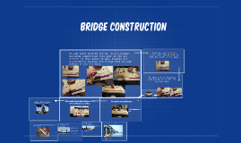
Transcript: The bridge did not withstand the 50 N specified. A more through plan and superior build quality would help improve structural rigidity. The design was kept relatively simple (apart from paper base), allowing ease when building. Initial concepts Triangular cross member throughout the bridge to help distribute the load. A lot of material was used to secure the paper down meaning the cost was high, £83,516. More time planning could have meant more efficient material use. Try not to rely on loads being applied perpendicular to a member without giving additional support. Using an Instron load cell, a vertical force was applied to the highest center point. The force would increase until the the resistive force from the bridge dropped, due to e.g. buckling, twisting or sheared joints. Vertical struts would distribute load throughout the base, where the bridge was strongest Maximum load of 40.9 N. Target of 50 N was not achieved. Poor joint construction caused them to fail under small loads. Strong base meant top strut warped considerably. Increase the length of the bridge past 500mm to allow for slippage. Final design The use of paper in this way still has potential. the use of larger paper sheet or more wedges between the frame and paper would have helped. Structural failure of base and one end of bridge dramatically reduced rigidity. Central strut succeeded in transferring load to base of bridge. Paper wasn't under enough tension to aid strength. Lack of symmetry causes twisting at puts additional stresses on one side of the bridge. Points of failure and success Results and potential improvements for next time Several 'steps' in load initially as joints began to fail. A load capacity of 50 N was required. The bridge would have to be at least 500mm to fit on support struts within load cell. Costs of materials meant there usage had to be kept minimal (no redundant material on bridge). Feasibility: would the design be feasible to construct out of the material provided? Balsa, paper and glue. Several consideration would have to be made whilst designing the bridge Extra length allowed for considerable bending without the bridge falling of its supports. Inclined triangular members at either end to distribute some of the load onto the paper fastenings. Testing to destruction Use papers tensile properties to support the bridge. Strips of paper would be placed on you underside of the bridge, which would be put in tension as the base buckles. Place the top member under compression by arching them upward, hence displacing the applied load in a horizontal direction. Bridge construction Paper covering the base was wrapped around either end.


